This article will guide you through connecting, calibrating, and using the NanoVNA as well as the NanoVNA Saver software.
Click here to download a printable version in Microsoft Word Format
If you don’t already have a NanoVNA, check out our article titled Buying a NanoVNA to get some recommendations on which model we recommend and what accessories you might want to purchase when you get one. There are also some Kindle eBooks A Guide to the NanoVNA and NanoVNAs Explained: A practical guide to Nano Vector Network Analysers that may also be of interest to you.
Calibrating the NanoVNA
You can do everything with a NanoVNA as a standalone piece of equipment without having to connect it to a computer. However, some things are easier when it is connected to a computer and you use a program like NanoVNA Saver, or NanoVNA App, so when possible, that is my recommendation. This article will concentrate on using NanoVNA Saver with a computer.
To calibrate the NanoVNA without a computer connection (my prefered method for calibration), turn the NanoVNA switch on, the screen should turn on and display the BIOS information.
After it loads the BIOS and finishes booting, you will usually see lines on a grid (depending on your settings).
Find the 3 metal calibration caps that were included with your NanoVNA.
Connect the OPEN calibration cap to the S11/Port 1 port (see picture for identification of caps).
The calibration connectors in the picture below are from left to right: Open, Short, Load, Coupler.
The open calibration cap has NO center conductor.
Screw it on until it stops, being careful not to over-tighten it. It just needs to be on snug, not tight. This cap ensures no signals can enter the S11 port for this test.
Use the attached “guitar pick” as a stylus and click anywhere on the screen.
A menu will pop-up on the right side of the screen
Click Calibrate, then select Calibrate from the next menu as well.
Click the Open button to calibrate the device with no input (0% return).
The OPEN button will now have a checked checkbox to indicate it has set this calibration.
The selection will automatically advance to the SHORT test button.
Remove the Open connector, and connect the included Short connector to the S11/Port 1 port (same port as before). The Short cap is the all-gold one with a center pin that is also gold and part of the cap. Screw it on, and gently push the cap in a little to make sure the floating center pin is seated well.
Click the SHORT menu item to calibrate the device with a shorted input (100% return).
The SHORT button will change to have a checked checkbox to indicate it has set this calibration.
The selection will automatically advance to the LOAD test button.
Remove the Short connector, and connect the included 50-ohm connector to the S11/Port 1 port (same as before). The 50-ohm cap is the one that is Silver AND Gold, with a center pin. Screw it on, and gently push the cap in a little to make sure the floating center pin is seated well.
Click the LOAD button to calibrate it with a load. The menu will advance to ISOLN (Isolation) test. If you need to use both ports for a passthrough test, connect the 2 SMA cables with the SMA Coupler and click the ISOLN menu item. If you don’t need the passthrough functionality, you can skip this calibration and click Done. Otherwise, run the ISOLN calibration, and then click Done. Then, click anywhere on the screen to exit the menus.
Install NanoVNA Saver on Windows
Click the link below to download NanoVNA Saver. For Windows machines, you want the one named NanoVNASaver.x64.zip
https://github.com/NanoVNA-Saver/nanovna-saver/releases
Extract this zip file to a folder, and then open the folder and find the nanovna-saver v0.X.X.exe where X.X is the version number for the software you downloaded. This is the file you will use to run the program in the future.
Connect the NanoVNA to your computer via USB-C to USB-A cord then turn the NanoVNA’s power switch on. The NanoVNA screen should populate.
Open the NanoVNA Saver program that you installed earlier.
It will start with a command line window which stays open while you are using NanoVNA Saver. You can ignore any errors in the command line section for now, just leave it open.
Once it launches the GUI, look at the bottom left for the Serial Port Control section.
If your NanoVNA is connected and powered on, NanoVNA Saver will usually list the correct serial port automatically. If not, you can select it manually from the drop-down, or click the Rescan button to let it try to find it again. Once the correct port is selected, click the Connect to device button. That button should change to say Disconnect now.
Sweep Settings
You will see default values under Sweep Control (top left corner of the program) for 50 KHz to 900 MHz, which are basically worthless since I can’t imagine when you would want to scan that much range. Don’t worry about this for now, we’ll change them later.
(Caveat – NanoVNA Saver is kind of a POS, so it crashes often. If it crashes, try restarting the program. If it keeps crashing, try power-cycling the NanoVNA)
In my examples, I will refer to the SO-239 connector since that is what I use. If you need a different connector, please exchange that for SO-239 where you see that example used. Connect the SMA to SO-239 adapter to the S11 port on the NanoVNA.
Connect the SO-239 end to the antenna you wish to test (connect the antenna only, no other devices should be connected at this time).
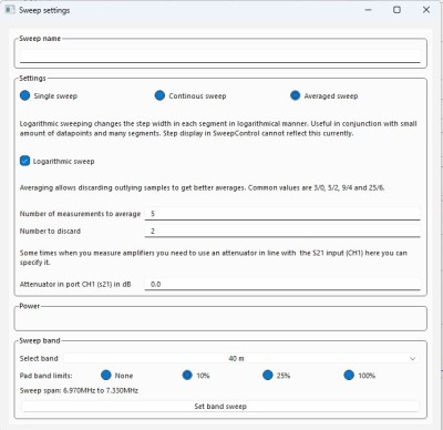
Click Sweep Settings at the top under Sweep Control
Select Averaged Sweep so we see an average of the sweep data. Single sweep will only perform one sweep and stop. Continuous sweep will do a continuous sweep until you stop it so you can see changes in real-time, which is interesting if you are playing with antenna location, or if you want to see the effect your body has on the antenna.
Select Logarithmic Sweep
Set Number or measurements to average = 5 (take 5 readings)
Set Number to discard = 2 (discard the 2 that are the most different from the other 3)
Select Band: Select any single band you want here, just so we can set the other options. For antenna tuning we will start with a larger range sweep than just the single band, so it doesn’t really matter what you select here, we will be changing it manually later.
If you will only be testing within a single band, you may want to set Pad limits to 10% which makes it automatically add an extra 10% to the band limits at the top and bottom to show a wider range than just that of the band definition.
Click Set band sweep button at the bottom. This saves all the options to the current sweep settings to the Sweep Control. The Sweep Settings window will NOT close, and the only change you will see is that the Sweep Control section at the top left now has different values than before.
Now that we have our other parameters set, you can close the Sweep Settings window manually or leave it open to make changes as you go. I usually close it out to save space on the monitor.
Display Setup
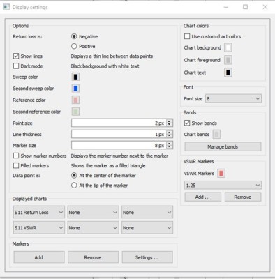
Click on the button labeled Display Setup at the bottom left
Look under VSWR Markers and use the drop-down list to see what values are already there.
If you do not have the following values, use the Add button to add them. 1.25, 1.5, 2.0, 2.5, 3.0
The Add VSWR window will pop-up and allow you to add additional values.
After entering a value, click the OK button to add it. To add more, repeat the 2 steps above until they are all added. This step will draw SWR lines in the chart so you can more easily see where your antenna is resonant.
Once you have added all the VSWR markers, you need to make sure the Show Bands option is checked in the Bands section of the main Display Settings window. This will make gray lines appear for the pre-defined Radio Bands within the sweep, which is helpful.
Change all other settings to those visible in the picture below.
Once complete, simply close the window to save the settings.
Conducting a Sweep
If you want to know what a multiband antenna will do, you will need to sweep more than one band’s range. For all of my examples below, I am using a 10 – 40M EFHW as an example.
At the top left, change the Sweep Control Start setting to read 3.0MHz (you can simply press 3m and it will know you mean 3.0 MHz) and Stop to be 30M (substitute the range of frequencies your antenna should cover, plus a little more at the top and bottom to start). You always want the start and stop frequency to be slightly higher and lower respectively than the range of the band so you have some space on each side of the chart.
Click the Sweep button (Not Sweep Settings) to execute a frequency sweep.
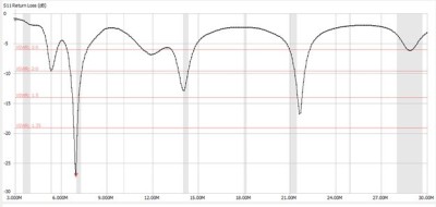
You will see the progress bar move in 20% increments (we are doing 5 sweeps) until it reaches 100%, you can now see the SWR of the antenna across it’s spectrum of use. Below is an example of an EFHW (End-Fed Half Wave) antenna I built that I was adjusting.
In the chart above, you can see the 4 horizontal red lines that we setup earlier to show us the SWR readings. You can also see the gray vertical lines that highlight the bands within that sweep range (3.5MHz/80M, 5.3MHz/60M, 7MHz/40M, 14MHz/20M, 18MHz/17M, 21MHz/15M, 24MHz/12M, 28MHz/10M). In the chart above, you can see that almost none of the bands are tuned perfectly on the antenna. But overall, it’s close on the bands most hams really care about, 40M, 20M 15M, 10M. When the dip happens before the band line (to the left of the band), it means your antenna needs to be shortened to move the line to the right (higher frequency resonant). If the dip is after the band line, you need to lengthen the antenna to move the dip to the left (lower frequency resonant). We want to keep everything under 3:1 SWR to be usable, but the lower the better, especially if you are tuning an antenna for a single band.
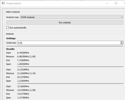
To quickly see what SWR’s you are dealing with, you can run an Analysis. Click the Analysis button at the bottom left just under all the readings, and select the settings you want to use. In the example below, you will see the Start and End frequencies for the VSWR limit you set, the Minimum (resonant frequency) and the Span that is under the VSWR limit you set.
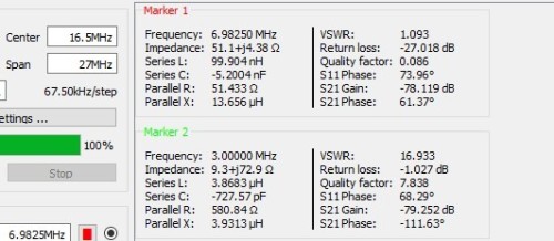
For this example the 40M band has a 3:1 SWR or less from 6.44250 MHz to 7.72500 MHz, which gives us a span of 1.28250 MHz, and a resonant frequency of 6.98250 MHz, whose SWR reading is 1.09.
When I have to trim my antenna, I usually find out what my resonant frequency is currently, so I don’t have to guess how much I need to trim, but instead have a S.W.A.G. (Scientific Will A** Guess) to start from. To find the resonant frequency just place a marker at the lowest point of the wave for the band you want and read the Marker 1 section on the readout for the Frequency that is at that marker you set (the little red triangle at 6.9MHz 2 pictures above).
In this example, the antenna is performing best at 6.98250 MHz. If I want to tune it to 7.1500 MHz (center of the 40M band) you would need to find the length for both frequencies in feet, then subtract the difference to know how much you need to remove. To find the length in feet we divide 468 by the frequency.
468 / 7.150 MHz = 65.4545 feet
468 / 6.9825 MHz = 67.0247 feet
Difference is 1.570 feet – so I would try folding back around ~1.5 feet and winding it around the main wire and test again. If it was perfect (or close to it) I would trim a little less than the indicated amount from the part of the wire that I had wound around itself and test again and again as I slowly cut an inch or so at a time to creep up on the perfect match. The extra length of wire that is wound around itself acts a lot like it was trimmed, but not exactly. So go slow. It is much easier to take more off than to put some back on. The more you do this, the better you will get at estimating how much to fold versus how much to trim.
For the example above, I am not making any cuts since the 15M band (which I use often during the day) is a little short already, which is why I split the difference to get a good all-around coverage antenna.
Also keep in mind if the wire you are using is copper or aluminum, not steel or Kevlar reinforced, it will likely stretch a little over time. It will also get slightly longer in hot weather, and slightly shorter in the cold.
If you make any adjustments or changes (angle of the slope, distance to ground, etc.) all you have to do to retest is click the Sweep button to run the tests again. If you want to retain the first reading to see how much of a change there is, before running the sweep again, click the Set current as reference button towards the bottom left before you run it again. It will show you this reference reading every time from then on as well as the current reading so you can see the overall difference.
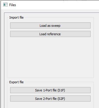
If you want to save the results for later use, simply click the Files button (bottom left) and select Save 1-Port file (S1P) and give it a meaningful name like the date, the antenna, its coverage, and any other notes (e.g. 20230429_EFHW_10152040_post_trim.s1p) or whatever format would make sense to you to know what it is a sweep or reference for. You can load that file later by selecting Files > Load as sweep or Load reference.
When you are finished using the NanoVNA, just unplug it and turn it off and store if somewhere safe. I recommend you always keep between a 40 – 60% charge on the battery when you know you will be storing the unit for a long time. Storing an LiPo battery for long periods of time fully charged can cause the battery to go bad prematurely and swell.
As always, there is a ton more you can learn about the NanoVNA. I highly recommend you check out some of the YouTube videos by Amateur Radio channels like Ham Radio Crash Course, or The Smoking Ape. These are 2 sources you can trust for great, unbiased information.
73,
N4MCP


